
Knowledge · Energy · 10/4/2026
Our photovoltaic installation: 32 panels, 4 MPPTs, batteries and Victron inverters
How our 13.92 kWp solar installation works: series-parallel panel wiring, how an MPPT charge controller works, Lynx 48 V distribution, Pylontech batteries and three MultiPlus-II units in three-phase.
The essentials in one image
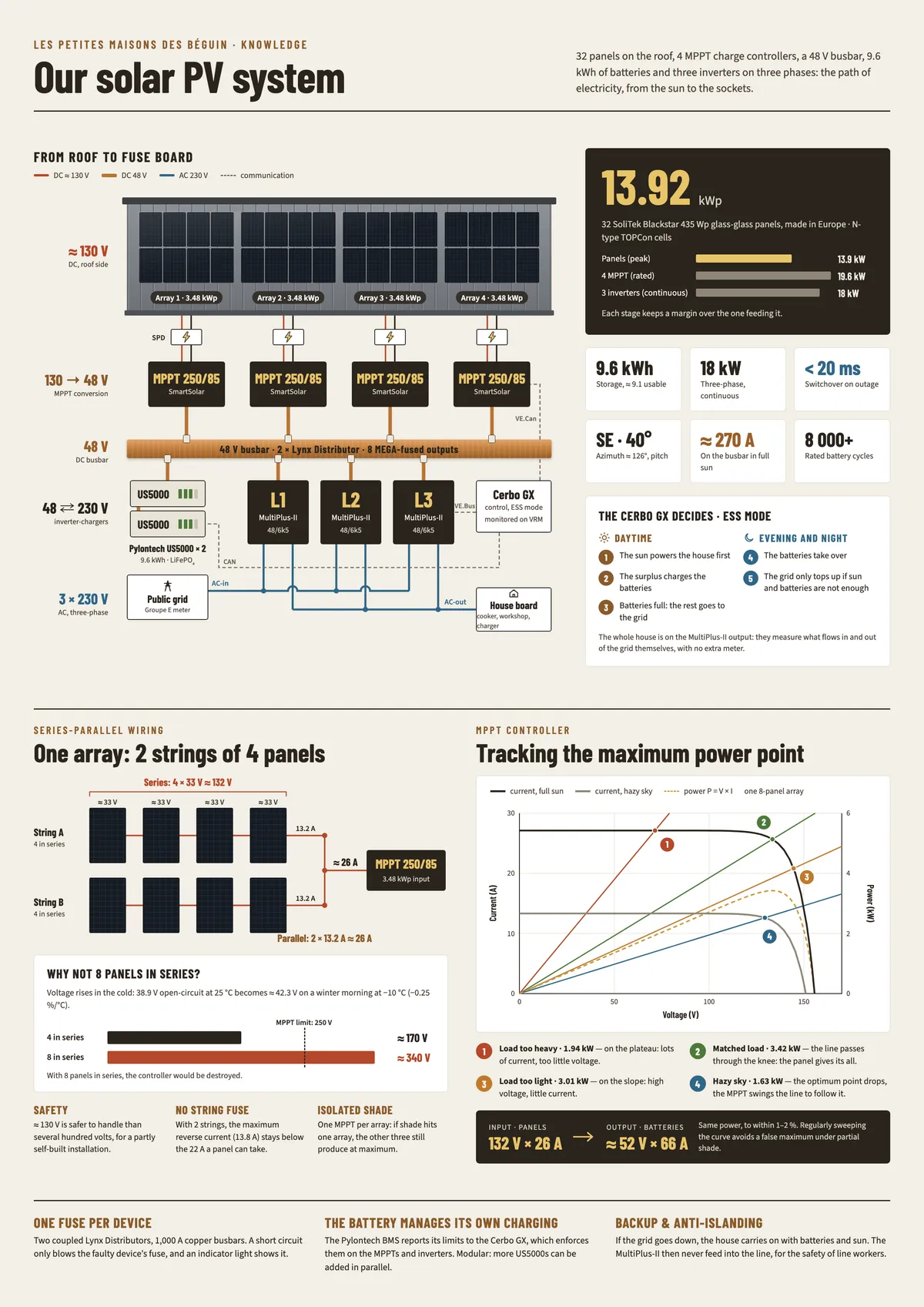 Enlarge the infographic
The roof of the house carries 32 solar panels. The electricity they produce goes through several devices before it reaches our sockets: charge controllers, a direct-current busbar, batteries and inverters. This article explains the role of each one and the reasons behind our wiring choices.
| Component | Choice |
|---|---|
| Panels | 32 × SoliTek Blackstar 435 Wp glass-glass, i.e. 13.92 kWp |
| Orientation | South-east (azimuth ≈ 126°), 40° roof pitch |
| Wiring | 4 fields of 8 panels, each made of 2 strings of 4 panels in series |
| Charge controllers | 4 × Victron SmartSolar MPPT 250/85 |
| DC distribution | 2 × Victron Lynx Distributor (48 V) |
| Storage | 2 × Pylontech US5000, i.e. 9.6 kWh |
| Inverter/chargers | 3 × Victron MultiPlus-II 48/6k5, one per phase |
| Control | Victron Cerbo GX |
Overview
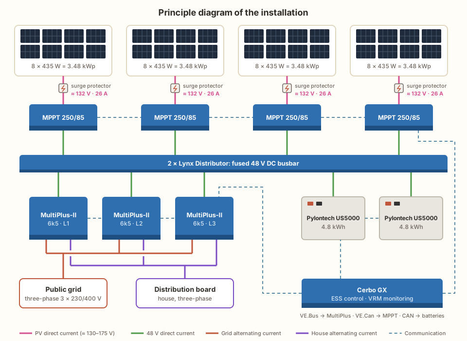
The installation works at two voltage levels. On the roof, the panels produce direct current at about 130 V. The MPPT controllers bring this voltage down to the battery voltage, around 48 to 54 V. The whole central part of the installation (controllers, batteries and inverters) is connected to a single 48 V busbar. Finally, the three MultiPlus-II inverters turn this direct current into 230 V alternating current, one per phase, for the house.
The panels: 32 modules in series-parallel
Our panels are SoliTek Blackstar 435 Wp modules, made in Europe. They are glass-glass modules (2 mm of tempered glass on each side), more resistant to ageing and hail than a conventional module with a backsheet. Their N-type TOPCon cells are bifacial. Mounted on a metal roof, however, they capture almost nothing from the back.
The 32 panels are fixed with rails to the steel roof sheets (swisspanels). They face south-east (azimuth ≈ 126°), on a roof pitched at 40°. With this orientation, production starts early in the morning and tails off earlier in the afternoon. This fairly steep angle favours production in winter, when the sun is low, and helps snow slide off.
| Panel characteristic (standard conditions) | Value |
|---|---|
| Power | 435 Wp |
| Voltage at maximum power (Vmpp) | 32.96 V |
| Current at maximum power (Impp) | 13.20 A |
| Open-circuit voltage (Voc) | 38.92 V |
| Short-circuit current (Isc) | 13.80 A |
| Voltage temperature coefficient | −0.25 %/°C |
| Maximum series fuse rating | 22 A |
| Dimensions | 1722 × 1134 × 30 mm |
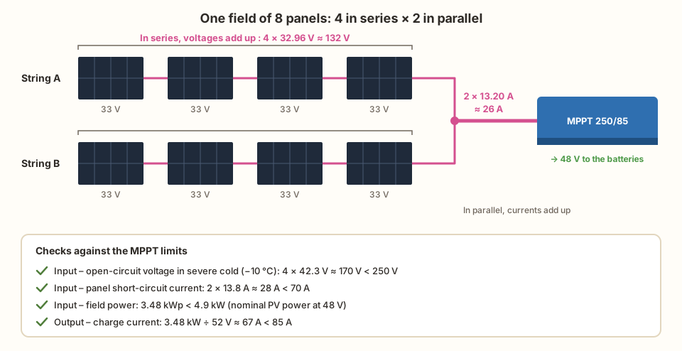
The panels are not all connected together. They are split into 4 fields of 8 panels, each connected to its own MPPT controller. In each field, the panels are wired as 2 strings of 4 panels in series, and the two strings are then connected in parallel:
- In series, voltages add up and the current stays the same. A string of 4 panels delivers about 4 × 33 V = 132 V.
- In parallel, currents add up and the voltage stays the same. Each string delivers about 13.2 A, so the two strings together deliver about 26 A.
Each field therefore represents 8 × 435 W = 3.48 kWp.
Why this layout?
The number of panels in series depends on the maximum input voltage the controller accepts: 250 V for the MPPT 250/85. But a panel’s voltage rises when it is cold. A panel showing 38.9 V open-circuit at 25 °C reaches about 42.3 V on a sunny winter morning at −10 °C. With 4 panels in series, the open-circuit voltage stays around 170 V in severe cold, with a comfortable margin. With 8 panels in series, it would approach 340 V and the controller would be destroyed.
This layout has other advantages:
- Safety: a voltage of about 130 V is easier and safer to handle than a string of several hundred volts, which matters for an installation we partly built ourselves.
- No string fuses: with only two strings in parallel, the current that could flow back into a faulty string cannot exceed the short-circuit current of the other string (13.8 A). That is less than what the panel can withstand (22 A). String fuses only become necessary from three strings in parallel.
- Fewer losses from shading: each field has its own MPPT. If a chimney or a tree shades one field, the other three keep producing as much as they can.
Each field is protected by a direct-current surge protector, placed before the controller. It diverts lightning surges to earth, to which the long cables coming down from the roof are exposed.
The MPPT controllers: getting the most out of the panels
A panel’s I-V curve
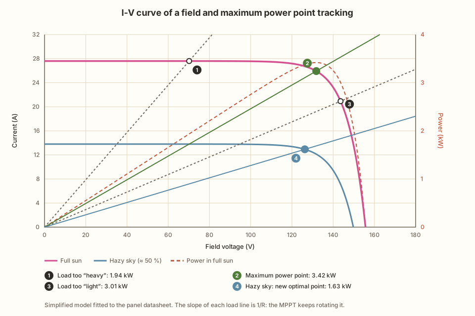
A solar panel does not behave like a battery delivering a fixed voltage. Its voltage and current depend on what is connected to it. It is described by its I-V curve (current as a function of voltage):
- On the left of the curve, the voltage is low and the current is almost constant, close to the short-circuit current. The panel behaves like a current source.
- On the right, the current drops quickly to zero, reached at the open-circuit voltage. The panel then behaves like a voltage source.
Power is the product of voltage and current (P = U × I). It is zero at both ends and peaks in the “knee” of the curve: this is the maximum power point (MPP).
The load line
Whatever is connected to the panel sets its operating point. A load that behaves like a resistance R follows Ohm’s law, I = U / R. On the graph, this is a straight line through the origin, with a slope of 1/R. The panel operates where this line crosses its I-V curve:
- Load too “heavy” (R too low, line too steep): the operating point sits on the flat part of the curve, with plenty of current but little voltage. A large part of the available power is lost.
- Matched load: the line goes exactly through the knee of the curve. The panel delivers all its power.
- Load too “light” (R too high, line too flat): the operating point sits on the falling part, with a high voltage but little current. Power is lost here too.
The maximum power point keeps moving: it drops when a cloud reduces sunlight (point 4), and its voltage changes with cell temperature. The ideal load line is therefore never the same from one moment to the next.
The role of the MPPT
If the panels were connected directly to the batteries, the battery voltage (about 52 V) would set the operating point, far from the 132 V of the optimal point. The MPPT (Maximum Power Point Tracking) controller sits between the two. It is an electronic converter that acts as a variable resistance as seen from the panels: by adjusting its conversion ratio, it rotates the load line.
In practice, it changes the voltage drawn from the panels very slightly, measures the resulting power and keeps going in the direction that increases it. It repeats this continuously, and so follows the maximum power point as clouds pass or the panels heat up. The SmartSolar also regularly sweeps the whole curve. This keeps it from getting stuck on a “local” maximum, which can appear when part of the field is shaded.
On the output side, the controller delivers the same power (minus 1 to 2 % of losses) at the battery voltage: 132 V × 26 A at the input become about 52 V × 66 A at the output.
Choosing the MPPT 250/85
We use 4 Victron SmartSolar MPPT 250/85, one per field. The name sums up the device’s two main limits, one on the panel side and the other on the battery side:
| Limit | Side | MPPT value | Our field |
|---|---|---|---|
| Maximum voltage (the “250”) | Input (panels) | 250 V | ≈ 170 V open-circuit at −10 °C |
| Maximum panel short-circuit current | Input (panels) | 70 A | 2 × 13.8 A ≈ 28 A |
| Nominal PV power at 48 V | Input (panels) | 4.9 kW | 3.48 kWp |
| Maximum charge current (the “85”) | Output (batteries) | 85 A | ≈ 67 A at most |
The four controllers are connected to each other and to the Cerbo GX through the VE.Can communication bus, which lets them charge the batteries in a synchronised way.
The Lynx Distributors: the 48 V backbone
At 48 V, power flows as high currents. At full production, the four controllers can send up to about 270 A to the 48 V busbar. The inverters can draw as much when they power the house from the batteries. This requires a sturdy, well-protected connection point.
That is the role of Victron’s Lynx Distributors. Each module contains two copper busbars, one positive and one negative, rated for 1,000 A. The positive busbar has four outputs, each protected by a MEGA fuse. We have coupled two of them, forming a single continuous busbar with 8 outputs:
- 4 outputs for the 4 MPPT controllers;
- 3 outputs for the 3 MultiPlus-II units (Victron recommends a 250 A fuse for a MultiPlus-II 48/6k5);
- 1 shared output for the 2 batteries, connected in parallel.
This setup has three advantages:
- Device-by-device protection: in the event of a short circuit, only the relevant fuse blows and isolates the faulty device.
- Short, symmetrical wiring: the heavy-gauge cables stay short, which limits losses and heating.
- Monitoring: one indicator light per fuse immediately shows a blown fuse.
The Pylontech batteries: storing the surplus
Storage relies on 2 Pylontech US5000 batteries. They are lithium iron phosphate (LiFePO₄) batteries, a chemistry known for its thermal stability and long life.
| Characteristic | One battery | Total (×2) |
|---|---|---|
| Nominal voltage | 48 V | 48 V |
| Nominal capacity | 4.8 kWh | 9.6 kWh |
| Usable capacity (95 % depth of discharge) | 4.56 kWh | ≈ 9.1 kWh |
| Continuous charge and discharge current | 100 A | 200 A |
| Rated lifetime | more than 8,000 cycles at 25 °C |
The two batteries are connected in parallel and share one output on the Lynx busbar. They communicate with the Cerbo GX over CAN bus. Their battery management system (BMS) continuously reports their state of charge and the charge and discharge currents they accept. The Cerbo GX passes these limits on to the MPPTs and the inverters. It is therefore the batteries themselves that set how they are charged.
The installation is modular: more US5000 batteries can be added in parallel if our needs grow.
The three MultiPlus-II units: the link with the house and the grid
The Victron MultiPlus-II 48/6k5 are bidirectional inverter/chargers. They can:
- turn the 48 V direct current from the batteries and panels into 230 V alternating current for the house;
- conversely, draw energy from the grid to charge the batteries if needed;
- feed surplus production into the public grid.
| Characteristic (one unit) | Value |
|---|---|
| Continuous output power at 25 °C | 6 kW (5.7 kW at 40 °C) |
| Peak power | 11 kW for 1 minute |
| Maximum battery charge current | 100 A |
| Maximum pass-through current from the grid | 50 A |
| Maximum efficiency | 96 % |
We have three of them, one per phase (L1, L2 and L3), configured together as a three-phase system. Together, the three units can supply 18 kW continuously from the batteries and panels. The house has a real three-phase supply, useful for the cooker, the workshop and the electric vehicle charger. The three units communicate with each other and with the Cerbo GX over the VE.Bus.
The MultiPlus-II units also include two safety functions:
- Switchover during a power cut: if the public grid fails, they disconnect from it and keep powering the house from the batteries and panels. The switchover takes less than 20 milliseconds, short enough that electronic devices do not switch off.
- Anti-islanding: during a power cut, they never feed current into the public grid. This is essential for the safety of technicians working on the lines.
The Cerbo GX: the conductor
The Cerbo GX is a small computer that coordinates all the devices. It runs Victron’s ESS (Energy Storage System) mode, which decides at every moment where the energy goes, in this order of priority:
- During the day, solar production powers the house first.
- The surplus then charges the batteries.
- Once the batteries are full, the rest is fed into the public grid.
- In the evening and at night, the batteries take over to power the house.
- The grid only supplies energy when the sun and the batteries are not enough.
To apply these rules, the system needs to know how much energy is exchanged with the grid. The official meter, at the connection point, is the one supplied by Groupe E. The whole house is connected to the output of the MultiPlus-II units, so everything entering or leaving the grid passes through the inverters, which measure it themselves. No additional meter is needed.
The Cerbo GX also sends its data to Victron’s VRM portal, where we follow production, consumption and battery status from a phone.
Summary
| Stage | Voltage | Device | Role |
|---|---|---|---|
| Roof | ≈ 130 V DC | 32 panels of 435 Wp in 4 × (2 × 4) | Produce 13.92 kWp |
| Conversion | 130 V → 48 V | 4 MPPT 250/85 | Track the maximum power point and charge |
| Distribution | 48 V DC | 2 Lynx Distributors | Connect and protect |
| Storage | 48 V DC | 2 Pylontech US5000 | Store 9.6 kWh |
| House and grid | 3 × 230 V AC | 3 MultiPlus-II 48/6k5 | Supply, exchange, back up |
| Control | — | Cerbo GX | Decide and monitor |
This architecture gives priority to using the energy produced on the roof on site. It stays connected to the public grid, which provides backup and absorbs the surplus. Each component can also be expanded separately if our needs change.