
Knowledge · Energy performance · 5/5/2026
Load-bearing straw construction: dimensions, density, lambda and μ factor
Technical characteristics of a straw bale wall: dimensions, density, thermal conductivity (lambda), μ factor, resistance R, U coefficient and hygrometric comfort.
The essentials in one image
 Enlarge the infographic
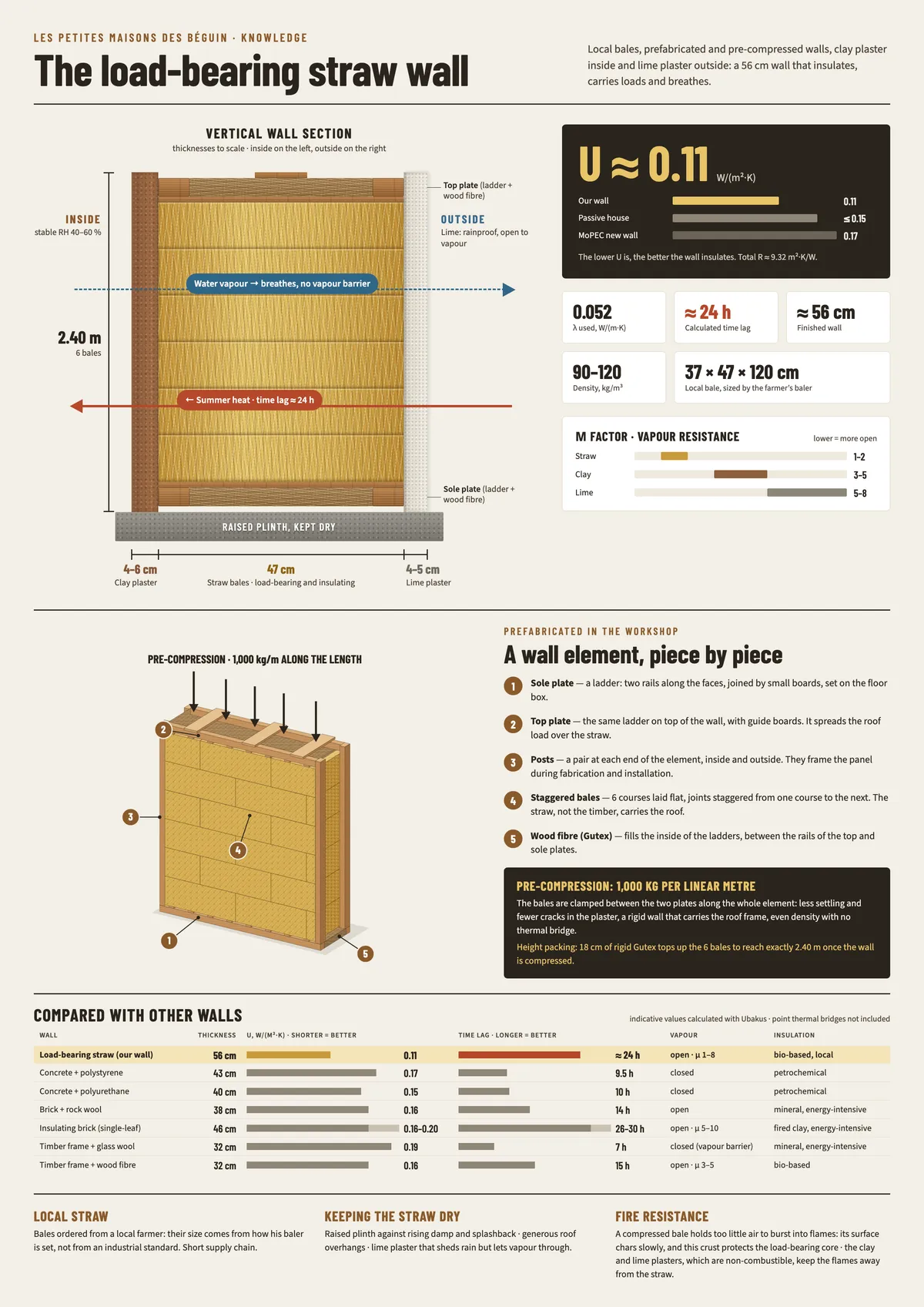
The load-bearing straw construction, combined with a raw earth plaster on the inside and a lime plaster on the outside, makes up a building system with specific thermal and hygroscopic properties. This article presents the technical characteristics of our build, made with prefabricated, prestressed straw walls.
| Characteristic | Value |
|---|---|
| Dimensions of a bale | 37 x 47 x 120 cm |
| Density | 90 to 120 kg/m³ |
| Thermal conductivity (λ) | 0.045 to 0.052 W/(m·K) |
| λ value used for the calculation | 0.052 W/(m·K) |
| μ factor (resistance to vapour diffusion) | About 1 to 2 |
| Thickness of straw in the wall | 47 cm |
| Thermal resistance of the straw (R) | About 9.04 m²·K/W |
| Thermal transmittance (U) of the wall | About 0.11 W/(m²·K) |
Wall composition
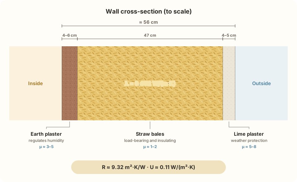
The exterior wall is made of three distinct layers, arranged from the inside to the outside to provide structure, insulation and humidity regulation all at once:
- Inner layer: 4 to 6 cm of raw earth plaster. This material naturally regulates relative humidity and provides surface thermal inertia.
- Wall core: 47 cm of baled straw. This thickness is the load-bearing element and the main insulating body.
- Outer layer: 4 to 5 cm of lime plaster. This mineral plaster protects the straw from the weather while remaining permeable to water vapour.
The total thickness of the wall is about 56 cm.
Origin and characteristics of the bales
The straw bales used for this project were bought directly from a farmer in the region. They are standard small bales, a very common format: their 37 × 47 cm cross-section matches the dimensions of the baler’s chamber, while their length varies slightly from one bale to the next.
- Measured dimensions: 37 × 47 cm cross-section, about 120 cm long.
- Density: between 90 and 120 kg/m³.
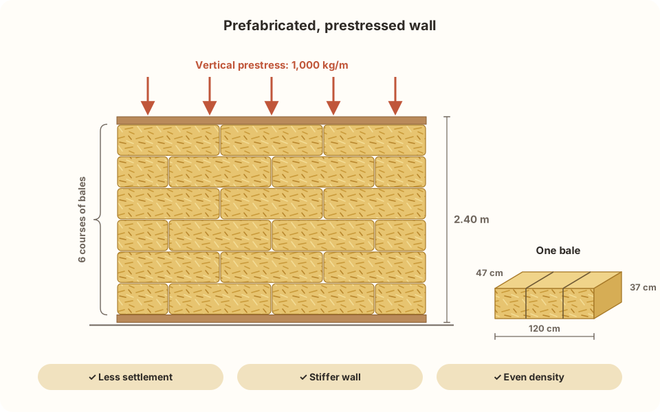
- Construction: the walls were prefabricated in the workshop. Vertical prestressing was applied to ensure the stability of the structure.
Straw is a by-product of cereal farming: it can be found almost everywhere, and getting hold of it is usually just a matter of asking a nearby farmer. This local availability keeps transport to a minimum and makes the material accessible to most projects.
Benefits of structural prestressing
A distinctive feature of this build is the prestressing applied when the wall panels were made. Each wall, 2.40 m high (the equivalent of a stack of 6 bales), was subjected to a compressive load of 1,000 kg per linear metre.
This prestressing has several technical advantages:
- Limiting settlement: the initial compression reduces the risk of later differential settlement, and so limits cracking in the plasters.
- Structural rigidity: it increases the cohesion of the whole, allowing the wall to carry the loads of the roof frame and ensuring the stability of the structure.
- Homogeneity: it guarantees a uniform density of straw over the full height of the wall, avoiding less dense zones that could create thermal bridges or mechanical weak points.
Thermal performance and calculation of the U-value
The thermal performance of the wall follows directly from the thickness of the straw and its density.
-
Thermal conductivity (lambda): for straw with a density between 90 and 120 kg/m³, the thermal conductivity is generally between 0.045 and 0.052 W/(m·K). For the calculation, we use the reference value from the professional rules for straw construction (RFCP, CP2012) for this density range, i.e. λ = 0.052 W/(m·K).
-
Thermal resistance (R): for a straw thickness of 47 cm, the thermal resistance is calculated with the formula R = e / λ:
- R_straw ≈ 0.47 / 0.052 ≈ 9.04 m²·K/W.
- Interior earth plaster (5 cm, λ ≈ 0.8 W/(m·K)): R_earth ≈ 0.05 / 0.8 ≈ 0.06 m²·K/W.
- Exterior lime plaster (4.5 cm, λ ≈ 0.87 W/(m·K)): R_lime ≈ 0.045 / 0.87 ≈ 0.05 m²·K/W.
- Interior and exterior surface resistances (EN ISO 6946): Rsi + Rse = 0.13 + 0.04 = 0.17 m²·K/W.
- Total resistance: R_total ≈ 9.04 + 0.06 + 0.05 + 0.17 ≈ 9.32 m²·K/W. The dense, conductive plasters contribute only about 1 % of this resistance: it is the straw that insulates.
-
Thermal transmittance (U): the U-value is the inverse of the total resistance (U = 1 / R_total).
- Calculation: U = 1 / 9.32 ≈ 0.107, rounded to 0.11.
- Result: U ≈ 0.11 W/(m²·K).
In Switzerland, the cantons’ model energy regulations (MoPEC/MuKEn) set a limit value of 0.17 W/(m²·K) for a new external wall when the envelope is assessed element by element: at 0.11 W/(m²·K), the wall is well below it. In France, the RE2020 sets no maximum U per wall; it assesses the building as a whole through overall indicators (Bbio, Cep), so a direct comparison with a wall U-value is not possible.
The passive-house standard (Passivhaus) is not defined by the U-value of a wall either, but by the performance of the whole house: a heating demand of at most 15 kWh/(m²·year), very good airtightness and a cap on primary energy. To get there, opaque walls with a U-value of around 0.15 W/(m²·K) or less are recommended. The straw wall falls within this recommendation, which is a good basis, but is not enough on its own to make a building passive.
Thermal lag and inertia
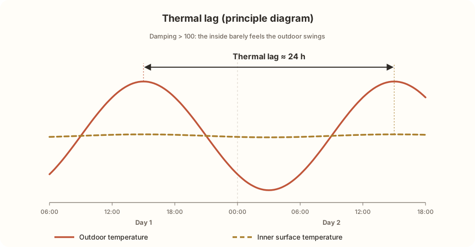
Thermal lag is the time it takes for a change in outdoor temperature to reach the other side of the wall. It is calculated according to EN ISO 13786, from the thickness, conductivity, density and heat capacity of each layer. The calculation also gives a second, often more telling indicator: damping, i.e. the factor by which the amplitude of temperature swings is divided as it passes through the wall.
- Calculated values: we modelled our wall with the online calculator Ubakus (earth plaster 5 cm, straw 47 cm with λ = 0.052 W/(m·K), ρ = 100 kg/m³ and c = 2,000 J/(kg·K), lime plaster 4.5 cm). The result is a thermal lag of about 24 hours and damping greater than 100. These are calculated, not measured, values: they depend on the assumptions made, in particular the heat capacity of the straw.
- Influence of thickness: thermal lag increases with thickness. With the same assumptions and 35 cm of straw, it would be about 19 hours.
- In practice: with damping greater than 100, a 15 °C swing between day and night outside results in less than 0.15 °C of variation on the inner face of the wall. Beyond a dozen hours, the exact thermal lag matters little: it is this damping that protects the inside from summer heat. Summer comfort then depends mainly on the windows (solar shading) and night-time ventilation.
λ: thermal conductivity; ρ: density; c: specific heat capacity, i.e. the energy needed to raise the temperature of 1 kg of material by 1 °C. The product ρ × c gives the amount of heat one cubic metre of material can store: about 0.2 MJ/(m³·K) for straw, compared with 2.4 MJ/(m³·K) for concrete.
Vapour permeability and indoor comfort
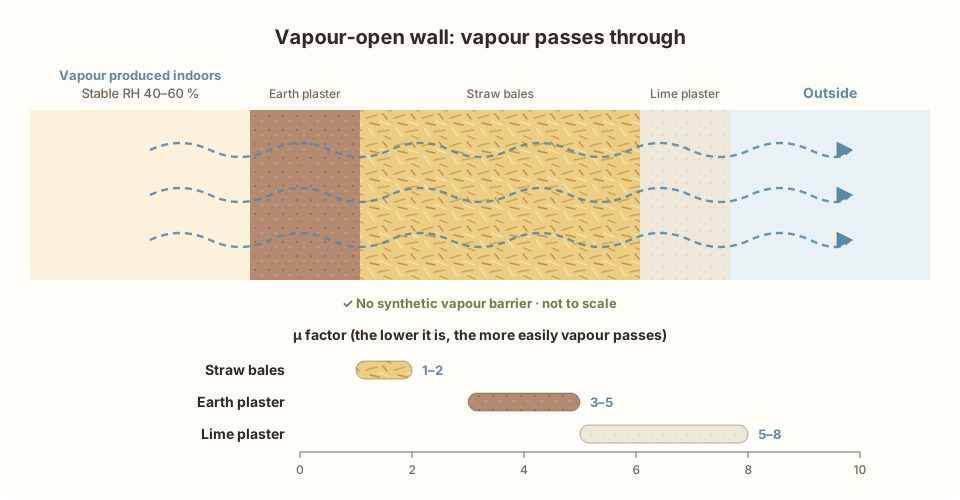
The design of the wall follows the principle of perspirance, that is, the ability of materials to let water vapour diffuse through.
- Vapour diffusion resistance factor (μ): straw has a very low μ factor (about 1 to 2), well below that of raw earth (3 to 5) and lime (5 to 8).
- Humidity management: this consistency of properties allows the water vapour produced inside the building to pass through the wall and escape to the outside, without meeting a blocking synthetic vapour barrier.
This allows a stable indoor humidity to be maintained, generally between 40 and 60 %, which contributes to occupant comfort and prevents the risk of condensation in the core of the wall.
Comparison with other wall types
To put our wall into perspective, the tables below compare it with exterior walls commonly built today, using the insulation thicknesses usually chosen to meet current requirements. The values are orders of magnitude: they vary with the chosen products and construction details.
The walls compared
| Wall type | Typical build-up (inside → outside) | Total thickness |
|---|---|---|
| Load-bearing straw (our wall) | Earth plaster 5 cm + straw 47 cm + lime 4.5 cm | ≈ 56 cm |
| Concrete + polystyrene (external insulation) | Reinforced concrete 20 cm + EPS 20 cm + render | ≈ 43 cm |
| Concrete + polyurethane | Reinforced concrete 20 cm + PIR 14 cm + ventilated cladding | ≈ 40 cm |
| Brick + stone wool | Fired clay brick 15 cm + stone wool 20 cm + render | ≈ 38 cm |
| Insulating brick (single-leaf) | Honeycomb clay brick 42.5 cm + plasters | ≈ 46 cm |
| Timber frame + glass wool | Plasterboard + vapour barrier + glass wool 24 cm between studs + board + cladding | ≈ 32 cm |
| Timber frame + wood fibre | Plasterboard + vapour retarder + wood fibre 24 cm + wood fibre board 6 cm + render | ≈ 32 cm |
Insulation
| Wall type | U (W/(m²·K)) |
|---|---|
| Load-bearing straw (our wall) | ≈ 0.11 |
| Concrete + polystyrene (external insulation) | ≈ 0.17 |
| Concrete + polyurethane | ≈ 0.15 |
| Brick + stone wool | ≈ 0.16 |
| Insulating brick (single-leaf) | 0.16 to 0.20 |
| Timber frame + glass wool | ≈ 0.19 |
| Timber frame + wood fibre | ≈ 0.16 |
Synthetic insulation allows thinner walls, but none of these common build-ups reaches the U ≈ 0.11 W/(m²·K) of our wall without a much thicker insulation layer.
Summer comfort
| Wall type | Thermal lag | Damping |
|---|---|---|
| Load-bearing straw (our wall) | ≈ 24 h | > 100 |
| Concrete + polystyrene (external insulation) | ≈ 9.5 h | > 100 |
| Concrete + polyurethane | ≈ 10 h | > 100 |
| Brick + stone wool | ≈ 14 h | > 100 |
| Insulating brick (single-leaf) | 26 to 30 h | > 100 |
| Timber frame + glass wool | ≈ 7 h | ≈ 6 |
| Timber frame + wood fibre | ≈ 15 h | ≈ 30 |
Every wall that combines substantial mass with good insulation (dense straw, single-leaf brick, concrete or brick insulated on the outside) divides outdoor temperature swings by more than 100. Lightweight timber frames damp far less: about 6 with glass wool and 30 with the denser wood fibre. At room level, however, summer comfort depends mainly on solar shading, internal mass and night-time ventilation: the wall is only one part of it.
Vapour management
| Wall type | Vapour permeability |
|---|---|
| Load-bearing straw (our wall) | Open (μ 1 to 8) |
| Concrete + polystyrene (external insulation) | Closed (μ EPS 20 to 100, concrete 80 to 130) |
| Concrete + polyurethane | Closed (aluminium facings) |
| Brick + stone wool | Open (μ ≈ 1) with a breathable render |
| Insulating brick (single-leaf) | Open (μ 5 to 10) |
| Timber frame + glass wool | Closed on the inside (vapour barrier) |
| Timber frame + wood fibre | Open (μ 3 to 5) |
Closed walls (vapour barrier, synthetic insulation) require perfect airtightness; a leak can trap moisture inside the wall. Vapour-open walls (straw, wood fibre, single-leaf brick) let vapour migrate and dry out naturally.
Origin of the materials
| Wall type | Insulation origin |
|---|---|
| Load-bearing straw (our wall) | Bio-based, local, stores carbon |
| Concrete + polystyrene (external insulation) | Petrochemical |
| Concrete + polyurethane | Petrochemical |
| Brick + stone wool | Mineral, energy-intensive manufacture |
| Insulating brick (single-leaf) | Fired clay, energy-intensive firing |
| Timber frame + glass wool | Mineral, energy-intensive melting |
| Timber frame + wood fibre | Bio-based |
Straw is a barely processed agricultural by-product that stores carbon, whereas cement, fired clay, mineral wools and petrochemical insulation require a lot of energy to manufacture.
Values calculated with the online calculator Ubakus: U according to EN ISO 6946, thermal lag and damping according to EN ISO 13786 (ratio between the temperature amplitudes of the outer and inner faces). Point thermal bridges not included. Properties used (λ in W/(m·K), ρ in kg/m³, c in J/(kg·K)): straw 0.052 / 100 / 2,000; reinforced concrete 2.3 / 2,400 / 1,000; EPS 0.035 / 20 / 1,450; PIR 0.022 / 32 / 1,400; fired clay brick 0.40 / 900 / 1,000; stone wool 0.035 / 100 / 1,030; honeycomb brick 0.07 to 0.09 / 650 / 1,000; glass wool 0.035 / 15 / 1,030; wood fibre 0.038 / 50 / 2,100; wood fibre board 0.046 / 230 / 2,100; spruce studs covering 15 % of the area. As Ubakus points out, these indicators are for comparing walls with one another and cannot predict the temperature of a room.
Durability and resistance
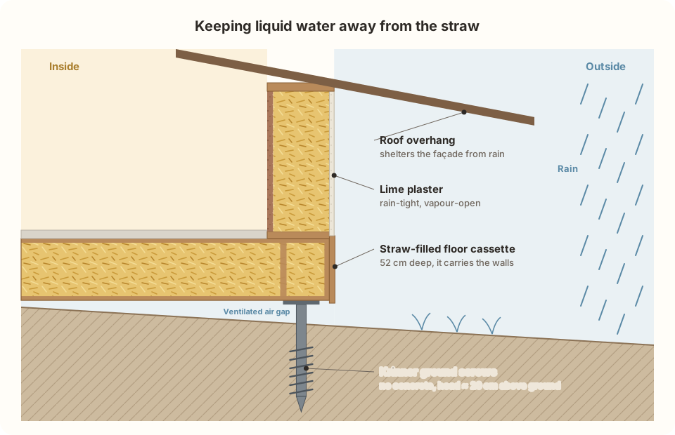
The durability of a straw wall depends on its protection against liquid moisture. The construction chosen includes:
- A base kept clear of water to keep the straw away from rising damp and rain splashes.
- Roof overhangs large enough to protect the facades.
- An exterior lime plaster that is impermeable to rainwater but permeable to vapour.
As for fire resistance, the high density of the straw (90–120 kg/m³) and the presence of mineral plasters on both sides limit combustion. In a fire, the surface layer of the plaster or the outer layer of the bale smoulders slowly, forming a charred layer that protects the core of the bale and maintains the load-bearing capacity of the wall for a significant time.
Conclusion
Using prestressed straw bales from local production, providing 47 cm of insulation, makes it possible to reach high levels of thermal performance (U ≈ 0.11 W/(m²·K)) with a calculated thermal lag of about 24 hours and very strong damping of temperature swings, while ensuring the structural stability of the building. Combined with natural plasters (earth and lime), this technique offers a coherent building system that controls heat and moisture flows, for a durable, energy-efficient building whose walls comfortably exceed the MoPEC requirements for building elements.